![]()
RADAR EQUATION
![]()
| Home | Products | Services | Technical Support | Profiles |
|
|
|
RADAR EQUATION |
| ||||||||
| ||||||||||
|
|
||||||||||||||||||||||||||
|
RADAR CROSS SECTION Radar cross section is the measure of a target's ability to reflect radar signals in the direction of the radar receiver, i.e. it is a measure of the ratio of backscatter power per steradian (unit solid angle) in the direction of the radar (from the target) to the power density that is intercepted by the target.
The conceptual definition of RCS includes the fact that not all of the
radiated energy falls on the target. A target's RCS (
RCS( Reflectivity: The percent of intercepted power reradiated (scattered) by the target. Directivity: The ratio of the power scattered back in the radar's direction
to the power that would have been backscattered had the scattering been uniform
in all directions (i.e. isotropically).
The RCS of a sphere is independent of frequency if operating at
sufficiently high frequencies where To reduce drag during tests, towed spheres of 6", 14" or 22"
diameter may be used instead of the larger 44" sphere, and the reference
size is 0.018, 0.099 or 0.245 m2 respectively instead of 1 m2.
When smaller sized spheres are used for tests you may be operating at or near
where For a flat plate which is frequency dependent , the RCS,
A sphere reflects equally in all directions. A flat plate that is perpendicular to the radar line-of-sight reflects directly back at the radar. A tilted plate reflects away from the radar. A corner reflects directly back to the radar somewhat like a flat plate. The sphere is essentially the same in all directions. The flat plate has almost no RCS except when aligned directly toward the radar. The corner reflector has an RCS almost as high as the flat plate but over a wider angle. Targets such as ships and aircraft often have many effective corners. Corners are sometimes used as calibration targets or as decoys, i.e. corner reflectors. An aircraft target is very complex. It has a great many reflecting elements
and shapes. The RCS of real aircraft must be measured. It varies significantly
depending upon the direction of the illuminating radar.
As shown in Figure 5, the RCS is highest at the aircraft beam due to the large physical area observed by the radar and perpendicular aspect (increasing reflectivity). The next highest RCS area is the nose/tail area, largely because of reflections off the engines or propellers. Most self-protection jammers cover a field of view of +/- 60 degrees about the aircraft nose and tail, thus the high RCS on the beam does not have coverage. Beam coverage is frequently not provided due to inadequate power available to cover all aircraft quadrants, and the side of an aircraft is theoretically exposed to a threat 30% of the time over the average of all scenarios. Typical radar cross sections are as follows: Missile 0.5 sq m; Tactical Jet 5 to 100 sq m; Bomber 10 to 1000 sq m; and ships 3,000 to 1,000,000 sq m. Again, Figure 5 shows that these values can vary dramatically. The strongest return depicted in the example is 100 m2 in the beam, and the weakest is slightly more than 1 m2 in the 135/225 positions. These RCS values can be very misleading because other factors may affect the results. For example, phase differences, polarization, surface imperfections, and material type all greatly affect the results. In the above typical bomber example, the measured RCS may be much greater than 1000 square meters in certain circumstances (90, 270). SIGNIFICANCE OF THE REDUCTION OF RCS If each of the range or power equations that have an RCS (
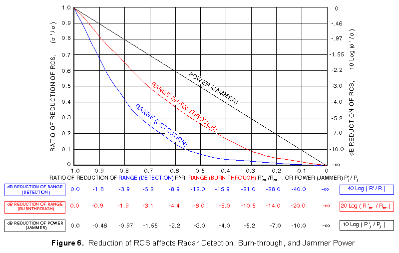 The equations used in Figure 6 are as follows: Range (radar detection): From the two-way range equation:
Range (radar burn-through): The crossover equation has:
Power (jammer): Equating the received signal return (Pr) in the two way range equation to the received jammer signal (Pr) in the one way range equation, the following relationship results:
Example of Effects of RCS Reduction - If the RCS of an aircraft is
reduced to 0.7 (70%) of its original value, then OPTICAL / MIE / RAYLEIGH REGIONS Figure 7 shows the different regions applicable for computing the RCS of a sphere. 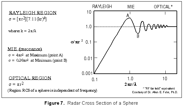 The optical region ("far field" counterpart) rules apply when 2 CREEPING WAVES The initial RCS assumptions presume that we are operating in the optical
region (  RADAR HORIZON / LINE OF SIGHTAs also shown in Figure 1, an aircraft may not be detected because it is below the radar line which is tangent to the earths surface. Some rules of thumb are: Range (to horizon):
Range (beyond horizon / over earth curvature):
In obtaining the radar horizon equations, it is common practice to assume a value for the Earth's radius that is 4/3 times the actual radius. This is done to account for the effect of the atmosphere on radar propagation. For a true line of sight, such as used for optical search and rescue, the constant in the equations changes from 1.23 to 1.06 (see later equations which round this to 1.05 for ease of computing). A nomograph for determining maximum target range is depicted in Figure 2. Although an aircraft is shown to the left, it could just as well be a ship, with radars on a mast of height "h". Any target of height (or altitude) "H" is depicted on the right side. 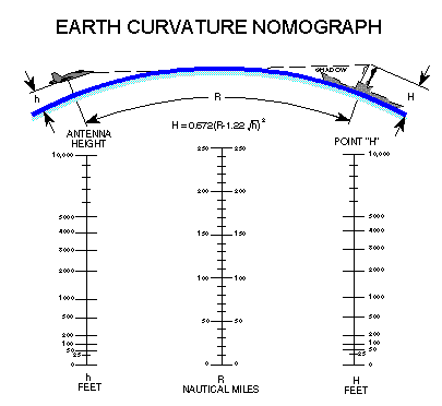 This data was expanded to consider the maximum range one aircraft can detect another aircraft in Figure 3. 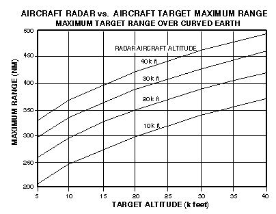
In this case "H" = 0, and the general equation becomes:
Where hr is the height of the radar in feet.
Figure 5 depicts the same for aircraft radars. It should be noted that most aircraft radars are limited in power output, and would not detect small or surface objects at the listed ranges. 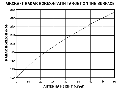 Other general rules of thumb are (with R in NM and aircraft altitude in feet): For Visual SAR: For ESM: |
||||||||||||||||||||||||||